Build a cell phone jammer
If you want to build a jammer yourself, then a circuit diagram is of course essential. So when we understand the circuit diagram, what is worth noting?
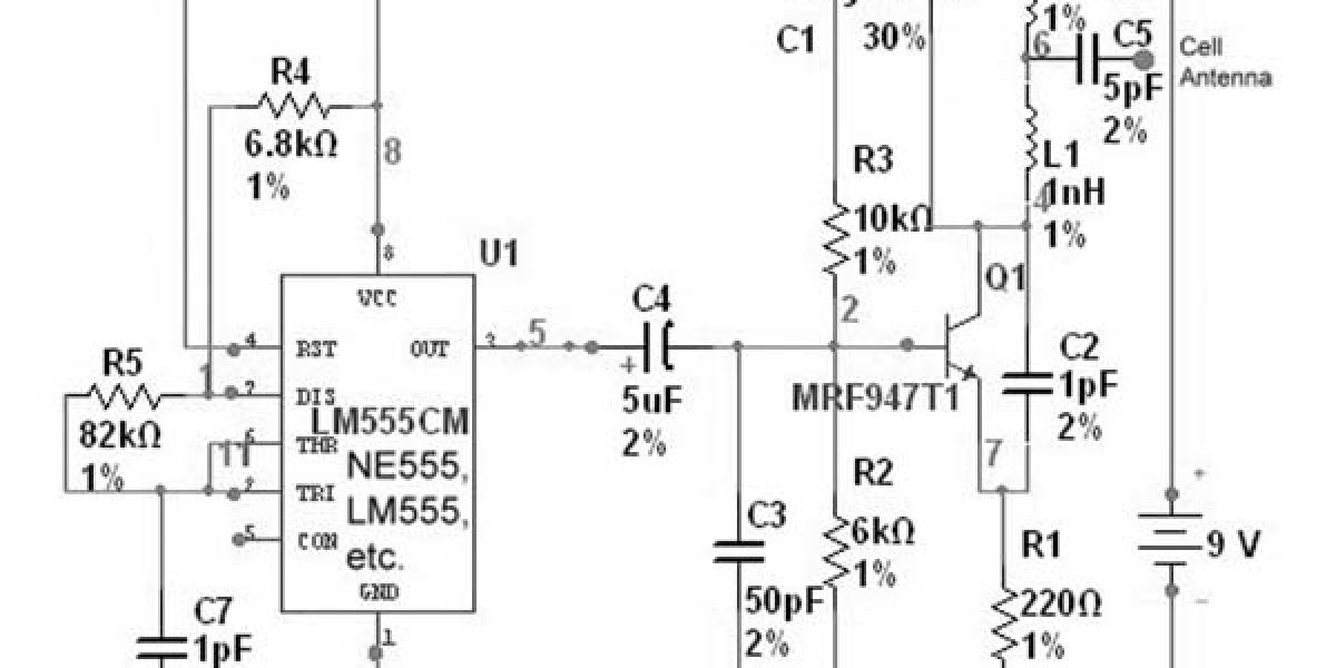
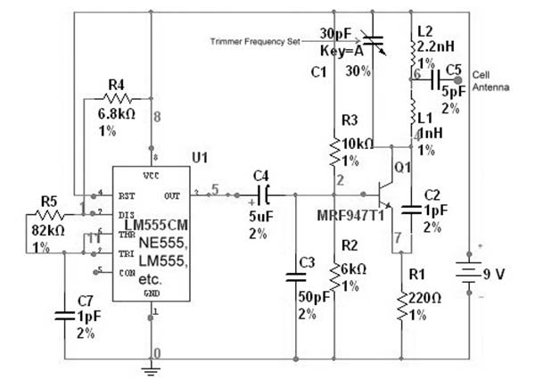
For any jammer circuit, remember that there are three main important circuits. When they are combined together, the output of that circuit will work as a jammer. The three circuits are
- RF amplifier.
- Voltage controlled oscillator.
- Tuning circuit.
Build a network jammer circuit
The oscillator or tuning circuit will generate a very high frequency with minimal damping. The inductor and capacitor of the tuning circuit will oscillate at their resonant frequency.
The tuning circuit operation is very simple and easy to understand. When the circuit is connected, the voltage is stored by the capacitor based on its capacity. The main function of capacitors is to store electrical energy. Once the capacitor is fully charged, it will allow charge to flow through the inductor. We know that inductors are used to store magnetic energy. When current flows through an inductor, it stores magnetic energy through the voltage at both ends of the capacitor and decreases. At some point, the inductor stores complete magnetic energy, and the charge or voltage at both ends of the capacitor will be zero.
The magnetic charge through the inductor will be reduced, and the current will charge the capacitor in opposite or opposite polarity. After another period of time, the capacitor will be fully charged, and the magnetic energy at both ends of the inductor will be completely zero. The capacitor will charge the inductor again and become zero. After a period of time, the inductor will charge the capacitor and become zero, and they will oscillate and generate frequency.
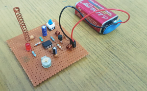
Start build a signal jammer
Simply program a small microntroller to generate a random-noise base signal and possibly the serial control strings for the PLL chip and wire it into the cellfone’s circuit. Ok, that part might be a little tricky, but a little collaboration with the online hacker community could easily produce diagrams for a handful of the more popular phones showing which wires to solder into to inject your rogue signal and activate the RF amp section etc… But all the hard work of creating the RF signal generator and amp and wave shaping circuits and antenna would already be done for you!
So worst case you would have an old cellfone with a small circuit board sandwiched to it externally which would have a PIC or other microntroller on it.
Or even better, invest some time into deciphering how to download a new firmware program into the phone’s main CPU. If you can do that, it would be simple enough to write a small program to do nothing more than send random noise, at full power, on the correct frequency.
An effective jammer does not necessarily need to be outputting a significantly higher power level than the devices it wishes to jam. most Cellfones use CDMA technology which means they are all essentially broadcasting on the same frequency, but they are all synchronized with the base station and transmit different “codes” within that frequency to allow the base station to decipher them individually. However, a single rogue phone on the CDMA frequency that is constantly blasting out garbage noise instead of carefully synched CDMA codes will drown out its immediate neighbors…